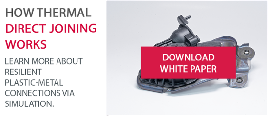
The increasing use of hybrid components made partly from metal and partly from plastic gives rise to the question of correct joint design. This applies in particular to components in which, in the interest of efficient production, the different materials are joined together in a thermal direct joining process during the injection molding process, without the use of mechanical joining elements or adhesives.
Modern development methods for metal components in vehicle construction have unleashed enormous efficiency potentials. Examples include modeling using the finite element method, virtual simulation testing, topology optimization and (partially) automated improvements with the help of AI and generative algorithms. These help to ensure a high degree of reliability when it comes to meeting whatever requirements have been set: strength, for instance, rigidity or formability, resource-saving use of materials and cost-efficient production. In this way, the number of prototypes and practical tests required has been minimized in recent years, saving costs and reducing development times.
Customer demands for greater sustainability in production and operation, and therefore the use of fewer materials and higher recycling rates, for example, are fueling the trend towards hybrid vehicle components (i.e. combinations of metals and plastics), as is the question of weight on account of the heavy batteries in electric vehicles. Fiber-reinforced thermoplastics in particular are being used here, as they can be processed on a large scale and are easy to recycle.
What is more, the joining process opens up promising possibilities for the design of components. It does, however, also present developers with new challenges. For one thing, existing models can no longer be used for the new material components. And for another, additional attention must be paid to connections between metals and plastics. For reasons of efficiency, direct thermal joining is recommended here instead of mechanical connections.
The fact that there are no additional joining elements such as bolts, rivets or adhesives provides a double advantage throughout the life cycle of the vehicle. In the first instance, it is more efficient to use the direct joining process to manufacture such hybrid or multi-material systems. This production method makes it possible to reduce cycle times, as the component is already joined when it is removed, so there is no need for any additional joining or assembly steps.
At the end of a vehicle's life, direct joining not only simplifies and accelerates the dismantling process of such hybrid components into their individual components but also enables the residual materials to be correctly sorted. The brief application of heat, by induction for example, heats the steel insert to above the melting point of the connected thermoplastic element and the individual components are separated without any further mechanical intervention.
However, if the hybrid components can be separated this easily, the question arises as to the reliability of the connection and the limits of its durability when in use. In other words, what forces it can withstand.
Modeling still in its infancy
A model-based simulation would be advantageous for exactly these questions. However, there are currently no established design methods for creating such joining zones. Research to date has concentrated on empirical experimental analyses of connection properties. Valuable knowledge gained from simulations has not yet been systematically incorporated into component and joint design. On account of the need for physical prototypes, non-standardized tests and empirical iterations, product development has therefore so far been very time-consuming and cost-intensive.
The research project "Methods and Design Criteria of Laser-Based Plastic-Metal Hybrid Joints for Customized Joints" (TailoredJoints), carried out between April 2020 and December 2022, addressed this deficit. The project developed a model-based design method for the design of plastic-metal joints with laser-structured metal surfaces. The method was tested on a joining process integrated into an injection molding process and evaluated using a close-to-production demonstrator made from an automotive seat structure. EDAG Engineering, the Institute for Machine Elements and System Development (MSE) at RWTH Aachen University, Cikoni, the Fraunhofer Institute for Laser Technology (ILT), Gubesch Thermoforming and Faurecia Autositze pooled their skills for the planning and execution of this project.
Microstructures for a micro-model
The material combination was a hot-rolled flat steel S420MC in accordance with DIN EN 10149-2 and a long glass fiber-reinforced polypropylene PP-GF30 already being used in the series production of seat structures. In a two-stage process, a laser was used to create structured recesses with a pronounced undercut, or microcavities, in the metal. The・CAE modeling・takes the form・of・a・micro・and・a・macro・model. The finite element (FE) micro-model describes the behavior of the joining zone at at microcavity level, based on data from microscopic cross-sectional examinations of cavity geometries after the laser structuring process.
The micro-model developed in this way was tested on the basis of validation studies. A special T-profile test body was developed for the tests. This made it possible to calculate the application-related individual load cases separately: head pull, peel stress and shear load. Compared to the results of the experiments, it was found that, in the simulation using the micro-model and a material card for PP-GF30, the strength of the joint was overestimated by a factor of 1.6 or 2.4 for head pull load and shear load respectively. An investigation into the causes revealed that a higher fiber content had been assumed in the cavities in the simulation model than was actually the case. Microscopic cross-sectional examinations showed that during the injection molding process, segregation of the glass fibers contained in the plastic compound occurs at the cavity edges near the joint boundary layer. 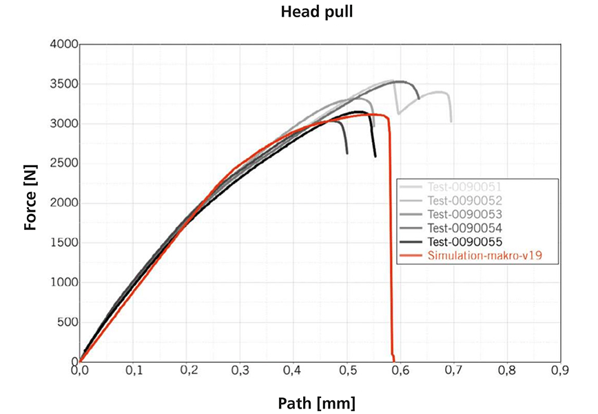
In further simulation tests with non-fiber-reinforced material models, it was seen that, with regard to the load cases to be applied, the selected approach for the micro-modeling of the joining zone is generally suitable for optimizing the joint at detail level. An accurate prediction of the joint strength at micro-level, however, calls for advanced modeling to realistically reproduce the fiber content and progression and the adhesive influences in the microcavities.
Macro-model at component level
The project partners also developed a macro-model to represent the behavior of the joining surface as a cohesive zone model, taking into account the failure behavior and making the development of the joint possible at component level. The parameters of this model were calibrated in two different ways. One was to transfer result data from the micro-model simulation and the other was to use the results of destructive tests on the joint in head pull and shear load cases on the T-Prohl test body. In the course of this validation process for fine adjustment of the macro-model, an accuracy of over 90 percent of the simulation was achieved with the experimental head pull and shear loads.
As the research project progressed, life cycle and cost analyses were also carried out, and the results transferred to a demonstrator. To this end, an electric height adjuster for a standard car seat was used. During production of the the seat height adjuster, a steel adapter plate is normally attached to the plastic housing with four screws, and this serves as a support for the entire torque of its motor/gearbox combination. In the project, this connection was created without the screws, using only direct thermal joining integrated into injection molding i.e. the force flow introduced runs solely across the direct joining surface.
Trial and error
The subsequent test program comprised the heat and aging treatment in a climatic chamber and a dynamic system test which simulates the twisting of the plastic housing in relation to the steel adapter plate in the event of a frontal impact. An average maximum torque of approx. 190 Nm between the adapter plate and the gearbox housing was identified. Here, too, there were deviations between the results of the model and the physical tests, and these led to an excessive, unfavorable peeling effect at the joint as a result of complex twisting of the metal adapter ring in a crash. 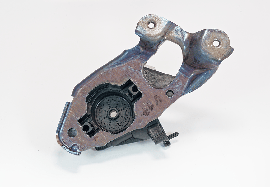
Further research must be carried out to clarify such complex influences, taking into account the overall component behavior (in this case taking the entire vehicle seat as our example). Nevertheless, it was possible to show that the model-based design method developed in the research project generally works and makes it possible to develop such innovative joints while at the same time optimizing process times and costs. 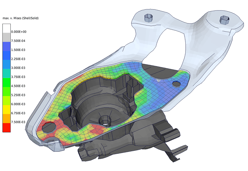
Conclusion
EDAG Engineering has acquired a wealth of expertise in the development of models and simulations to support the development process. These skills are being continuously expanded and intensified, now also for use in the design of hybrid components.
Are you also working with hybrid components and interested in efficient development and production processes for joints made of metal and fiber-reinforced thermoplastics? Then contact Michael Begert, Innovations Manager for Polymer Materials at EDAG Engineering, to discuss the correct designs for production using direct thermal joining integrated into the forming process. Further information can also be found in our white paper "Durable Plastic-Metal Connections by Simulation", which will provide you with more in-depth details on the progress of the research project and the findings obtained. 