When designing components, conserving energy and material is now an obligation. Using computer-based simulation procedures makes it possible to configure the shape of a component for minimal material use – this is referred to as topology optimization. If there are errors in this process, then there will be failures in practical application, if the component does not withstand the forces that occur. Such problems can be avoided by following the three basic rules of topology optimization.
To conserve energy and resources, alternative drive concepts such as eMobility and fuel cells are not the only key aspects. The only way for companies in the automotive industry and aerospace industry to compete successfully in the long term is to combine such concepts with reductions in the weight of components. In this regard, nature shows us the way: Nature succeeds in creating structures that can withstand enormous forces with minimal material usage. When developers attempt to follow these construction principles, we call it bionic design. However, attempts to optimize topology do not always meet with success.
At the EDAG Group, engineers have been dealing with this issue for years. For example, together with Jack Wolfskin the "EDAG Cocoon" concept car was introduced to the public in 2015: It was a fully functional vehicle based on the concept of an organic skeletal structure. Material usage was reduced to only that which was required for function, safety, and rigidity. This lightweight construction passenger vehicle emphatically demonstrated the possibilities that arise from an intelligent mix of conventional design and bionic design.
How topology optimization works
Since 2015 the design and simulation software has been consistently further developed and today it offers the user many possibilities, including support through suitable AI processes. Use of the finite element method (FEM) has become the de facto standard for topology optimisation. With this method, the component is divided into a finite number of small parts, known as finite elements, which are interconnected by nodes. The net-like structure that occurs in this process is referred to as "meshing". The next step integrates the boundary conditions, such as fixation of the component and consideration of the forces acting on the component.
Based on these conditions, equations that best describe the particular physical problem are then set up for each finite element. Given the shape and the point at which forces act on the element, relationships arise between load and the resulting displacement, i.e. deformation, of the respective element. These displacements can then be converted into stresses and strains of the component using the constitutive equation.
For topology optimisation, the next step is to use artificial intelligence based on intelligent algorithms. Artificial intelligence analyzes the existing stress values and thus filters out the points of the component that are subject to the highest loads. Here the algorithm adds precisely enough material so that the areas can withstand the loads.
Risks associated with automatic design processes
One problem with this procedure is that optimization occurs for a single load case. For moving parts in particular, the acting force and/or the direction of action can change – and this changes the entire load situation. If this is not taken into account in development, the component will indeed function in principle, but it will only function for one specific static load case. If the component then moves into a different position through motion in the machine, hazardous stress peaks can occur, which in practical application cause the component to fail. This takes up valuable time in the development process and drives up costs.
Therefore, at EDAG, before starting topology optimization, an analysis of the initial situation is first carried out – this is one of the most important steps for target-oriented product development. This involves the force application points, the force, direction, type of stress and boundary conditions being determined in the design and calculation department at the very outset. After the evaluation of the initial situation has been completed, the component can, in the design phase, already be designed in such a way that the most favorable basic shape possible is created for the subsequent topology optimization, without having to make any compromises in terms of safety. Thus, topology optimization becomes an effective component of product development.
Proven design principles
For example, one approach is considering the interior section modulus of the component relative to bending stresses. This is presented as the quotient of geometric moment of inertia and the distance of the neutral phase to the edge of the component. The geometric moment of inertia critically dependent on the component's basic geometry and should be individually calculated or looked up for each component shape. The geometric moment of inertia is incorporated directly into the general formula for bending stresses, so that it is possible to derive the points at which material can be saved.
An additional finding of EDAG's design department: If installation space allows, from the design perspective a tensile load should be preferred over a compressive load. The formula description for tensile load and compressive load differs only in the algebraic sign of the acting force. The breaking point for soft materials is characterized by constriction or flow of the component under tensile load, however the component can buckle under compressive load.
If the installation space is insufficient for a component subjected to tensile load, then the only possibility is compressive load. In this case pay attention to the type of fixation in the optimization process. Based on the type of fixation, four different types of "buckling" can be differentiated.
Structural elements made of strong or high-strength materials must be subjected to very rigorous analysis for both compressive loads and tensile loads. With such structural elements fracture occurs without any apparent warning, resulting in immediate failure of the component. Consequently, to the extent possible, soft materials should be used for safety-relevant components, , because they show early indications of constriction (at tensile load) or deformation (at compressive load).
At EDAG we investigated the problem of torsional stress with different software solutions. However, the result was always the same, relative to torsional stresses the tube is already the ultimate in terms of lightweight design. Here you should rely on a closed profile – either a tube or a shaft.
The 3 basic rules of topology Optimization
At EDAG the following three rules, in particular, have proven to be effective for the design of tensile load / compressive load components and subsequent topology optimization.- 1. Tensile load is preferred over compressive load
- 2. Use soft materials if possible
- 3. Pay attention to fixation for compressive loads.
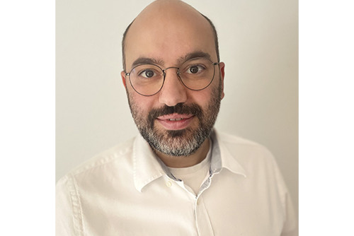
Andreas Raifegerst, Team leader development at EDAG aeromotive Gmbh, is well-versed in the complexity of topology optimisation and the particularities of the design process. Contact him if you have questions concerning this process. Or download the whitepaper "The 3 Basic Rules of Topology Optimization", in which he explains the practical application of these design principles using a specific component and the corresponding formulas.


